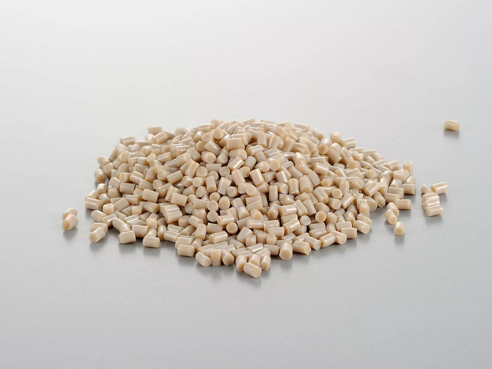
1、Transparent or uneven-colored pure resin parts.
The transparent or uneven color of the parts is caused by insufficient crystallinity or inconsistent crystallinity of the materials. The issue can be optimized or solved by increasing the temperature of the mold and controlling a consistent temperature of each mold section.
2、Stratification.
In the thin-wall structure of the parts, when there is too much melt flowing by and there is excessive shear in the relatively cold melt, the polymer between different thicknesses is insufficiently combined to form layers of different crystal structures. Under certain conditions, the surface part are spalling/peeling. The issue is mainly solved by adjusting the gate position and part wall thickness.
3、Ablative dark spots.
Ablative dark spots occur in welded line zones, at the end of flow paths, or in individual molded part zones (e.g., the rib). Sometimes the parts are also incompletely filled. The reason is the injected plastic melt pushes air to the front of the cavity before it can escape and is compressed. This air gets very hot and causes ablative dark spots on the parts. The issue can be solved by reducing injection rate, adjusting exhaust groove depth or properly designing the exhaust groove.
4、Black spots.
Abnormal black spots are observed on natural-colored or light-colored products. This may be caused by material contamination, carbonization etc. It is necessary to check if the material is contaminated, if the equipment is defective or too large, and if the equipment is worn. Identify the specific cause and fix it, and the issue may be remediated.
5、Color difference, commonly seen as gloss difference or stress whitening.
Potential causes include over pressure preservation, too small draft angle, too few or unreasonable ejector pins design, vacuum between the parts and the mold during extrusion. Adjust the process or mold structure accordingly and the issue can be solved.
6、Snakelike stripes.
This happens when the cavity is designed such that there is a melt transition from thin to thick, nothing disturbs the melt and the melt has a very high flow rate. The polymer melt is injected into the free cavity in a jet flow. If it contacts and sticks to the mold wall, or gradually cools and is unable to combine with the subsequent melt, the first injected melt is squeezed onto the surface, resulting in snakelike stripes on the part surface. Snakelike stripes not only result in poor appearance, but also in reduced strength. This issue can be effectively solved or mitigated by designing the mold properly or by using a lower injection rate when filling the corresponding zone.
7、Cold materials.
The reason is that melt at low temperature being deheated and solidified in the machine nozzle or hot runner. During the next injection, the deheated material is brought into the part cavity to form a cold material zone. As the cold material part cannot be well fused with other melts, the mechanical properties of the part is impacted. This problem can be effectively mitigated or solved by designing the nozzle temperature properly, reasonably rolling back screw after plasticizing and setting cold material well.
8、Aeration
Aeration in the parts may be caused by too high plasticizing or injection rate. When plasticizing, appropriate plasticizing rate and back pressure should be selected to avoid introducing air into the melt. During injection, especially when there is thin to thick transition in the cavity, the injection rate should be lowered when filling this zone.
9、Shrinkage marks or vacuum pores.
Shrinkage marks and vacuum holes usually appear at the thickest parts due to insufficient material filling. When the solidified material of the edge layer yields to the shrinkage force, shrinkage marks are generated, and vacuum holes are generated otherwise. Effective solutions include increasing holding pressure, extending holding time, and reasonably designing the melt filling path to avoid thin to thick transitions, etc.
10、Wavy stripes.
There are two main situations when the part surface forms wave stripes perpendicular to flow direction. One is when a too low injection rate result in excessive cooling of the front melt, a close fitting to the cavity wall is no longer possible during filling. The other is, when the cavity flow ratio is too large, the melt at the back of the cavity has high viscosity and large pressure loss, the mold filling cannot effectively fit the cavity wall. Setting a reasonable injection rate and increasing melt temperature and mold temperature are effective solutions to alleviate or solve the issue.
11、Water vapor stripes.
Water vapor stripes are thin and long streaks that usually appear on the part surface in the direction of melt flow. The issue can be alleviated or eliminated by sufficiently drying material particles or setting a reasonable temperature in the hopper area.
12、Floating fiber.
On the surface of fiber reinforced products, rough spots or areas are shown uniformly or unevenly and obvious bare fibers are observed under a microscope. This issue can be effectively alleviated or eliminated by increasing melt temperature, mold temperature, or injection rate.
13、Tiger stripes.
Tiger stripes appear perpendicular to the melt flow direction. They are alternate matte and bright stripes named for its resemblance to markings on tiger skin. They are mainly caused by melt pulsation flow and indirectly by insufficient melt propulsion pressure. This issue can be effectively alleviated or eliminated by increasing gate size and increasing melt and/or mold temperature.
14、Underpouring.
This is manifested by incomplete cavity filling. The issue can be effectively alleviated or solved by increasing runner number, increasing gate size and number, increasing melt and mold temperature, increasing injection rate and replacing with a brand with better fluidity.
15、Warping deformation.
This is manifested by deviation of the part from design shape, such as distortion or warping. The direct cause is varied shrinkage effect of different part areas. The deep cause may be inconsistent material crystallinity, non-uniform mold temperature or melt filling, stress balance caused by filling path, unreasonable material selection, etc. Adjusting mold temperature, pressure preservation, cooling cycle, reasonable designing mold structure and choosing a low warpage brand accordingly can effectively alleviate or solve the issue.


